


Product name : CHINA FACTORY HYDRAULIC CONTROL VALVE
Product No. : 2022528143412
Details:
Overview of Hydraulic Control Valves
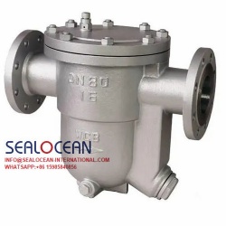
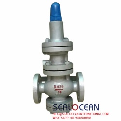
The hydraulic control valve is a valve controlled by water pressure. The hydraulic control valve consists of a main valve and its attached conduits, pilot valves, needle valves, ball valves and pressure gauges. According to the purpose, function and place of use, it can be evolved into remote control float valve, pressure reducing valve, slow closing check valve, flow control valve, pressure relief valve, hydraulic electric control valve, water pump control valve, etc. A filter should be installed before the hydraulic control valve, and it should be convenient for sewage discharge. This type of valve should generally be installed horizontally in the pipeline.
Principle and structure of hydraulic control valve
The hydraulic control valve is a valve that opens, closes and adjusts the pressure of the pipeline medium as the driving force. It consists of a main valve and attached conduits, needle valves, ball valves and pressure gauges, etc. According to the purpose of use and different functional places, it can be evolved into a remote control float valve, pressure reducing valve, slow closing check valve, flow controller. , pressure relief valve, hydraulic electric control valve, emergency shut-off valve, etc. The pilot valve moves with the change of the liquid level and pressure of the medium. Since there are many types of pilot valves, they can be used alone or in combination, so that the main valve can be used to adjust the water level, water pressure and flow independently and compositely. . However, the main valve body is similar to a globe valve. When the valve is fully opened, its pressure loss is much larger than other valves, and the closer the loss coefficient of each opening is to the fully closed state, the more sharply it increases, and the larger the valve diameter, the greater the pressure loss. Significantly.
The valve with the above characteristics is prone to the impact of water hammer when the action close to the valve disc is accelerated, and when it is close to fully closed, the slower the valve action, the better, so a throttling device can be installed on the valve disc. In addition, the throttling and action part of the pilot valve should try to avoid setting the orifice with extra small diameter to avoid clogging. If necessary, add a filter screen, regularly repair and set up a bypass pipeline. The hydraulic control valve is divided into two types: diaphragm type and piston type. The working principle is the same. The pressure difference between the upstream and downstream is the power. The valve disc is fully open or fully closed or in regulation.
When the pressure water entering the control chamber above the diaphragm (piston) is discharged to the atmosphere or the downstream low pressure area, the pressure acting on the lower part of the disc and below the diaphragm is greater than the pressure above, thus pushing the main valve disc to the full Open position: When the pressure value entering the control chamber above the diaphragm (piston) is in the middle of the inlet pressure and the outlet, the main valve disc is in a regulating state, and its regulating position depends on the combination of the needle valve and the pilot valve in the catheter system. control effect.
The pilot valve can open or close its own small valve port through the change of downstream pressure, thereby changing the pressure value of the control chamber above the diaphragm (piston) and controlling the adjustment position of the main valve disc. It can be used for domestic water supply, fire protection system and industrial water supply system.
Material of hydraulic control valve parts
| Part Name | material |
| valve body, valve cover | Cast iron, cast steel, stainless steel |
| valve seat | Tin bronze, stainless steel |
| Disc | Carbon steel, stainless steel + nitrile rubber |
| stem | Aluminum green steel, chrome stainless steel |
| Diaphragm | Nitrile rubber |
| Diaphragm pressure plate | carbon steel, stainless steel |
| spring | Stainless steel |
Selection points of hydraulic control valve
1. The hydraulic control valve used in the engineering type is a product that has passed the inspection of the manufacturer, has complete various signs, and meets the requirements of technical data.
2. According to the functional requirements, select the type of valve, and then determine the material of the valve body and sealing part of the valve according to the pipeline transportation medium, temperature, building standards and major requirements of the industry. Commonly used valve body materials are cast iron, copper iron, copper, plastic and so on. Commonly used sealing surface and lining materials are copper alloy, plastic, steel, cemented carbide, rubber, etc. The valve body material should match the piping material.
3. The nominal pressure of the valve has different levels such as 0.6, 1.0, 1.6, 2.5 and 4.0MPa. The working pressure of the medium conveyed by the pipeline should be less than the nominal pressure value of the valve.
4. The setting of the hydraulic control valve in the project should have enough space for management, operation, installation and maintenance, and should meet the requirements of the pipeline for the valve.
5. When the pipeline is connected by flange, the hydraulic control valve with flange connection should be used; when the pipeline is connected with groove, the hydraulic control valve with groove connection should be used.
6. The hydraulic control valve should be set on the pipeline where the medium flows in one direction.
7. The direction of the arrow on the main valve body of the hydraulic control valve must be consistent with the flow direction of the pipeline system.
8. There should be no gas blockage or gas blockage in the pipe section connected to the hydraulic control valve. An automatic exhaust valve should be installed in the gas storage section such as the high position of the pipe network.
9. When the valve is installed horizontally, the valve cover and valve stem should face upwards. When installed vertically, the valve cover and valve stem should face outward.
10. The strength and tightness test should be done before the valve is installed.
Classification characteristics of hydraulic control valve
According to the structure, the hydraulic control valve can be divided into two types: diaphragm type and piston type. The working principle is the same. The pressure difference between the upstream and downstream is △P as the driving force, and is controlled by the pilot valve, so that the hydraulic differential operation of the diaphragm (piston) is completely controlled by hydraulic pressure. Automatically adjust so that the main valve disc is fully open or fully closed or in a regulated state. When the pressure water entering the control chamber above the diaphragm (piston) is discharged to the atmosphere or the downstream low pressure area, the pressure acting on the bottom of the valve disc and under the diaphragm is greater than the pressure above, so push the main valve disc to fully open When the pressure water entering the control chamber above the diaphragm (piston) cannot be discharged to the atmosphere or the downstream low pressure area, the pressure value acting on the diaphragm (piston) above is greater than the pressure value below, so the main valve disc will be removed. Press to the fully closed position; when the pressure value in the control chamber above the diaphragm (piston) is between the inlet pressure and the outlet pressure, the main valve disc is in a state of adjustment, and its adjustment position depends on the needle valve in the conduit system and adjustable The combined control function of the pilot valve. The adjustable pilot valve can open or close its own small valve port through the downstream outlet pressure and with its change, thereby changing the pressure value of the control chamber above the diaphragm (piston) and controlling the adjustment position of the square valve disc.
Technical characteristics of hydraulic control valve
In the mode of action, the pressure of the medium in the hydraulic control valve and the operation of the hydraulic system are used, and it can be automatically controlled, with accurate action and reliable performance.
Technical parameters of hydraulic control valve
| Nominal pressure (Mpa) | Shell test pressure (MPa) | Sealing test pressure (MPa) | Applicable media | Medium temperature (℃) |
| 1.0 | 1.5 | 1.1 | water | 0-80 |
| 1.6 | 2.4 | 1.76 | ||
| 2.5 | 3.75 | 2.75 | ||
Dimensions of hydraulic control valve
| DN | L | A | A1 | H | H1 | F | D mm |
D1 mm |
D2 mm |
n-Φd | ||||||||
| mm | mm | mm | mm | mm | mm | PN1.0 | PN1.6 | PN2.5 | PN1.0 | PN1.6 | PN2.5 | PN1.0 | PN1.6 | PN2.5 | PN1.0 | PN1.6 | PN2.5 | |
| 20 | 180 | 330 | 130 | 550 | 460 | 116 | 105 | 105 | 105 | 75 | 75 | 75 | 58 | 58 | 56 | 4-13.5 | 4-13.5 | 4-14 |
| 25 | 180 | 330 | 130 | 550 | 460 | 116 | 115 | 115 | 115 | 85 | 85 | 85 | 68 | 68 | 65 | 4-13.5 | 4-13.5 | 4-14 |
| 32 | 180 | 330 | 130 | 550 | 460 | 116 | 140 | 140 | 140 | 100 | 100 | 100 | 78 | 78 | 76 | 4-17.5 | 4-17.5 | 4-18 |
| 40 | 240 | 345 | 135 | 610 | 516 | 170 | 150 | 150 | 150 | 110 | 110 | 110 | 88 | 88 | 84 | 4-17.5 | 4-17.5 | 4-18 |
| 50 | 240 | 345 | 135 | 610 | 516 | 170 | 165 | 165 | 165 | 125 | 125 | 125 | 102 | 102 | 99 | 4-17.5 | 4-17.5 | 4-18 |
| 65 | 250 | 355 | 140 | 625 | 520 | 180 | 185 | 185 | 185 | 145 | 145 | 145 | 122 | 122 | 118 | 4-17.5 | 4-17.5 | 8-18 |
| 80 | 285 | 360 | 146 | 645 | 538 | 210 | 200 | 200 | 200 | 160 | 160 | 160 | 133 | 133 | 132 | 8-17.5 | 8-17.5 | 8-18 |
| 100 | 360 | 400 | 156 | 750 | 596 | 275 | 220 | 220 | 235 | 180 | 180 | 190 | 158 | 158 | 156 | 8-17.5 | 8-17.5 | 8-22 |
| 125 | 400 | 420 | 170 | 808 | 655 | 310 | 250 | 250 | 270 | 210 | 210 | 220 | 184 | 184 | 184 | 8-17.5 | 8-17.5 | 8-26 |
| 150 | 455 | 435 | 186 | 864 | 710 | 355 | 285 | 285 | 300 | 240 | 240 | 250 | 212 | 212 | 211 | 8-22 | 8-22 | 8-26 |
| 200 | 585 | 480 | 206 | 1135 | 805 | 460 | 340 | 340 | 360 | 295 | 295 | 310 | 268 | 268 | 274 | 8-22 | 12-22 | 12-26 |
| 250 | 650 | 530 | 226 | 1185 | 855 | 500 | 395 | 405 | 425 | 350 | 355 | 370 | 320 | 320 | 330 | 12-22 | 12-26 | 12-30 |
| 300 | 800 | 575 | 246 | 1325 | 955 | 580 | 445 | 460 | 485 | 400 | 410 | 430 | 370 | 370 | 389 | 12-22 | 12-26 | 16-30 |
| 350 | 860 | 620 | 275 | 1385 | 990 | 640 | 505 | 520 | 555 | 460 | 470 | 490 | 430 | 430 | 448 | 16-22 | 16-26 | 16-33 |
| 400 | 960 | 635 | 286 | 1445 | 1030 | 715 | 565 | 580 | 620 | 515 | 525 | 550 | 482 | 482 | 503 | 16-26 | 16-30 | 16-36 |
| 450 | 1075 | 665 | 320 | 1325 | 905 | 780 | 615 | 640 | 670 | 565 | 585 | 600 | 532 | 550 | 548 | 20-26 | 20-30 | 20-36 |
| 500 | 1075 | 695 | 348 | 1430 | 960 | 830 | 670 | 715 | 730 | 620 | 650 | 660 | 585 | 585 | 609 | 20-26 | 20-33 | 20-36 |
| 600 | 1230 | 720 | 372 | 1565 | 1020 | 920 | 780 | 840 | 845 | 725 | 770 | 770 | 685 | 685 | 720 | 20-30 | 20-36 | 20-39 |
| 700 | 1650 | 770 | 422 | 1755 | 1160 | 980 | 895 | 910 | 960 | 840 | 840 | 875 | 800 | 800 | 820 | 24-30 | 24-36 | 24-42 |
| 800 | 1750 | 805 | 458 | 2230 | 1515 | 1050 | 1015 | 1025 | 1085 | 950 | 950 | 990 | 905 | 905 | 928 | 24-33 | 24-39 | 24-48 |